FREE DOWNLOAD – B.F.S. HOLDING
Explore the full spectrum of services and industries covered by B.F.S. Holding.
The structural integrity and longevity of any construction project depend fundamentally on the quality of concrete placement. Choosing the correct types of concrete pouring equipment is not merely a logistical decision; it is a critical engineering calculation that impacts project timelines, labor costs, and—most importantly—the final strength of the cured element. Modern construction, driven by ambitious vertical and horizontal scale, demands specialized machinery capable of handling vast volumes of material while maintaining strict quality control over the final mix properties, such as slump consistency and temperature. For a leading organization like B.F.S industries, understanding these systems is paramount to delivering holistic construction solutions that integrate formwork with advanced pouring techniques. This guide offers an expert-level analysis of the primary equipment categories used across the industry today, focusing on operational performance, efficiency gains, and best-practice field application.
1. Concrete Pumping Systems: The Core of Modern Placement
Concrete pumps represent the most transformative category in modern placement technology, offering unparalleled speed and reach for both horizontal and vertical distribution. These hydrostatic devices use powerful pistons or a rotary system to move semi-liquid concrete through specialized pipelines, overcoming the limitations imposed by conventional methods. The principal advantage lies in the continuous flow of material, which is essential for large monolithic pours and rapid-cycle construction schedules. Proper management of the pumping system is key to preventing blockages and ensuring a steady pouring rate control at the destination, safeguarding the structural homogeneity of the element being cast.

1.1. Boom Placer Pumps: The Agility Factor
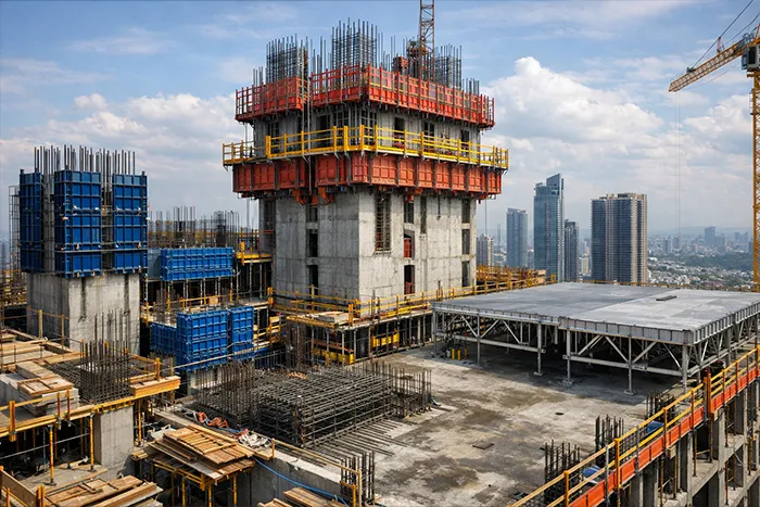
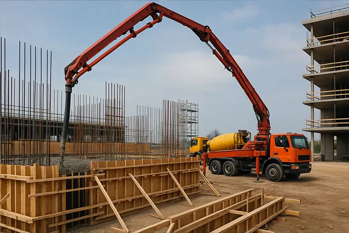
Boom placer pumps are truck-mounted, self-contained units equipped with a hydraulic articulating arm (the boom) that unfolds to reach precise, elevated, or distant pouring locations. This equipment is indispensable for high-rise buildings, bridge decks, and large-slab foundations where material needs to be distributed over a wide area from a single setup point. Their mobility and rapid deployment significantly reduce reliance on external crane support and manual labor, making them a cornerstone of time-sensitive and logistically complex construction projects, particularly those involving intricate tunnel formwork system supplier setups where quick cycle times are non-negotiable.
1.1.1. Operational Nuances and Rate Control
Effective pump operation depends on preemptive line management, including lubricating the pipes with slurry before the concrete arrives to minimize friction and wear. The operator must meticulously monitor the pressure gauges and flow rates, adjusting the hydraulic output to match the formwork’s acceptance capacity. Maintaining a consistent pouring rate control is critical for mitigating the risk of cold joints, pressure buildup, and excessive formwork loading, which can lead to blowouts or deformation, thereby ensuring a perfect, uniform lift.
1.2. Line Pumps and Trailer-Mounted Units: Versatile Application
Line pumps, often trailer-mounted or smaller truck-mounted units, are designed for jobs requiring high pressure and long-distance conveyance, typically utilizing steel or flexible hoses laid out across the site. They are commonly employed for pouring basement slabs, ground-level pads, and remote sections of a site where a boom pump cannot easily access or set up its outriggers. These units are highly flexible, capable of pushing concrete through hundreds of meters of pipeline, making them a cost-effective alternative for smaller or more geographically challenging pours.
1.2.1. High-Pressure Pumping for Vertical Lifts
When concrete must be pumped vertically to upper floors, the required pressure increases dramatically with the lift height and the specific gravity of the mix. For these demanding applications, the concrete mix design must be highly pumpable; this requires strict control over the water-cement ratio and aggregate grading to achieve the correct slump consistency. High-pressure line pumps must be regularly inspected for pipe wear and coupling integrity to prevent catastrophic failures, which can interrupt the pour and compromise the structural element being cast.
2. Material Transport and Agitation Equipment
The transportation of ready-mix concrete from the batching plant to the construction site is a crucial process, as the mix must be continuously agitated to prevent premature setting and segregation. The specialized equipment in this category ensures the material arrives at the point of placement with the specified rheological properties and temperature. Failure in this chain leads directly to compromised strength and workability, negating the effort of subsequent placement tools. The efficiency of ready mix concrete transport is directly linked to the batching plant’s capacity and the site’s logistical readiness.

2.1. Transit Mixers: Maintaining Homogeneity
Transit mixers, universally recognizable as ‘cement trucks,’ are the backbone of ready mix concrete transport, consisting of a rotating drum mounted on a truck chassis. The drum continuously agitates the concrete during transit at a slow ‘agitation speed’ (typically 2-6 revolutions per minute) to ensure the aggregates, cement, and water remain uniformly suspended. This agitation prevents the heavy aggregates from settling (segregation) and stops the cement from undergoing hydration prematurely, preserving the specified slump consistency until the concrete reaches the pump or placement zone.
2.1.1. Drum Speed and Capacity Considerations
The optimal drum speed must be balanced; excessive rotation can entrap air and potentially over-mix the concrete, slightly reducing its final strength, while insufficient rotation leads to segregation. Standard transit mixers in most markets carry between 6 to 10 cubic meters of material, and their route must be carefully managed to ensure the concrete is discharged within the maximum permitted transit time (usually 90 minutes) from water addition, a critical factor for quality assurance.
2.2. Agitator Trucks and Volumetric Mixers: Point of Pour Control
While similar in appearance to transit mixers, agitator trucks transport already-mixed concrete but do not have the capability for on-board mixing; their drum is designed purely for agitation. Volumetric mixers, conversely, transport the raw ingredients (sand, gravel, cement, water) separately and mix the concrete on demand at the construction site. These mixers are particularly useful for remote sites or projects requiring numerous small, intermittent pours, allowing for precise adjustment of the mix design immediately before discharge.
2.2.2. Quality Control at the Point of Pour
The use of volumetric mixers allows for unparalleled quality control as the final mixture and slump consistency can be tailored right at the formwork. This capability is vital when pouring specialized elements, such as those associated with the installation of large columns, where a slight adjustment to the mix workability is necessary to ensure complete filling of complex mold geometries, a factor often considered when dealing with a Circular Column Formwork Supplier.
3. Cranes and Conventional Placement Methods
Before the widespread adoption of concrete pumps, or in specific site conditions where pumping is impractical (e.g., extremely high lifts, very stiff concrete, or remote placement requiring non-pumpable aggregate sizes), conventional methods relying on lifting equipment remain relevant. These methods typically involve batching the concrete into a container and physically lifting and guiding the container to the pour location.

3.1. Crane-Hoisted Concrete Buckets: Precision for Tall Structures
The use of a concrete bucket hoisted by tower cranes or mobile cranes provides an effective means of transporting concrete to great heights or wide-reaching spans, common in the construction of cooling towers or specialized bridge pylons. These heavy-duty buckets are equipped with bottom gates controlled by the operator, allowing for precise, gravity-assisted placement of the material directly into the formwork. The operator coordinates closely with the signaler to ensure the drop height is minimized, thus reducing the risk of material segregation.
3.1.1. Effective Load Management and Swing Control
Safety and efficiency hinge on precise crane operation and effective communication. The bucket’s capacity must be carefully calculated against the crane’s safe working load, especially at maximum reach. Controlling the swing and descent of the concrete bucket is paramount, particularly in windy conditions or near vertical formwork. Furthermore, regular inspection of all hoisting rigging and the mechanical integrity of the bucket’s discharge mechanism is a non-negotiable part of safety during concrete pouring operations.
3.2. Conveyor Belts for Horizontal Distribution
In large, low-level construction projects, such as dam construction, industrial flooring, or large pavement works, belt conveyors offer a continuous, high-volume method for horizontal distribution. Specialized conveyor systems for concrete use a hopper at the feed end and a controllable discharge chute, allowing the material to be moved efficiently across significant distances at grade. They are valued for their high throughput and ability to be easily extended or retracted based on the evolving pour requirements.
3.2.2. Minimizing Segregation and Belt Maintenance
Unlike standard aggregate conveyors, concrete conveyors must be designed with raised sides and a smooth surface to minimize friction and prevent aggregate from separating from the mortar. The angle of incline must be kept shallow (ideally less than 30 degrees) to prevent slump consistency from being compromised by rapid movement or excessive vibration. Consistent cleaning and inspection are required to prevent dried concrete buildup, which can lead to misalignments and costly downtime.
4. Specialized Methods for Challenging Environments
Certain projects—particularly those involving deep foundations, underwater construction, or constrained access—demand specialized equipment and methodology beyond standard pumping or bucket techniques. These methods prioritize control, density, and the exclusion of environmental contaminants.
4.1. Underwater Pouring via the Tremie Pipe
The tremie method is a highly effective technique used for placing concrete underwater, such as for mass concrete elements like coffer dams, bridge pier foundations, or sealing a caisson. This system utilizes a large-diameter pipe (the tremie pipe) with a sealed top, lowered vertically into the water. Concrete is fed into the pipe, creating a continuous seal (or plug) that prevents water from coming into direct contact with the fresh concrete, thereby eliminating washout and segregation risks.
4.1.1. Tremie Pipe Design and Initial Charging Procedures
The success of the tremie method hinges on maintaining a continuous flow and ensuring the pipe remains deeply embedded in the placed concrete below. The pipe’s diameter must be large enough to allow free flow without blockages, yet small enough to be manageable. The initial charge requires careful placement of a “pig” or ball plug to maintain the seal as the pipe is filled, ensuring the first batch of concrete displaces the water without mixing, establishing a clean interface for the entire pour.
4.2. Concrete Placement Tools and Vibratory Consolidation
Once the concrete is placed into the formwork, a secondary set of concrete placement tools is essential for shaping and compacting the material to remove entrapped air, a process known as consolidation. This compaction process is critical for achieving maximum density, strength, and durability. Equipment ranges from simple hand tools like shovels and screeds to sophisticated powered devices.
4.2.1. Vibratory Consolidation and Concrete Placement Tools
The most important of these are vibrators, which liquefy the concrete temporarily, allowing it to flow around rebar and fill all voids. Internal ‘poker’ vibrators are common for beams and columns, while external formwork vibrators are used for thin, pre-stressed elements or for complex tunnel formwork system supplier sections where internal access is limited. Choosing the correct vibrator frequency and duration is vital; under-vibration leads to honeycombing, while over-vibration can cause harmful aggregate segregation.
5. Case Study: High-Rise Core Wall Pumping with a Boom Placer
The Challenge and Solution
A recent high-rise project in a densely populated urban area required the construction of a 60-story reinforced concrete core wall with an extremely aggressive construction schedule (four-day cycle). The challenge was twofold: reliably lifting the concrete over 200 meters and ensuring a uniform pouring rate control for the high-tolerance slip-form system. The general contractor chose a combination of a stationary high-pressure line pump on the ground level, feeding a dedicated hydraulic boom placer mounted atop the core structure. This system minimized ground disruption and allowed the pump operator direct visual access to the placement zone.

Execution and Equipment Synergy
The concrete was delivered to the site via transit mixers, which discharged directly into the ground pump’s hopper. The mix design utilized superplasticizers to maintain a high slump consistency (180mm) without compromising strength, facilitating the extreme vertical pump. The stationary pump lifted the concrete to the boom placer, which then distributed the material within the confines of the core formwork with surgical precision. This highly optimized system utilized a digital pressure monitoring loop, achieving a predictable pouring rate control of 15 cubic meters per hour, ensuring a flawless, joint-free core wall without any observable Cracks During Concrete Pouring or cold joints upon inspection.
6. Pre-Pouring Equipment Inspection Checklist
Before commencing any concrete pour, a rigorous inspection of all equipment is mandatory to prevent delays and catastrophic failure. This process is a core component of safety during concrete pouring protocols and should be documented thoroughly.
Pre-Pour Checklist
This is a simplified checklist for pre-pour readiness across multiple equipment types.
| Item | Equipment Type | Inspection Point | Status (Y/N) |
|---|---|---|---|
| 1 | Pump/Line | Pipe couplings and seals (no leaks or excessive wear) | |
| 2 | Mixer/Truck | Drum rotation and brake function; discharge chute clear | |
| 3 | Boom Placer | Hydraulic fluid levels; boom articulation pins and sleeves | |
| 4 | Vibrator | Power source connection; cable integrity; head functionality | |
| 5 | General Site | Adequate wash-out facility and emergency shut-off accessibility |
7. Comparative Analysis of Major Concrete Placement Tools
Choosing between the available types of concrete pouring equipment requires a deep understanding of project-specific constraints—notably volume, reach, and speed. The table below summarizes the trade-offs between the primary placement solutions.
| Equipment | Primary Use Case | Max Vertical Reach | Max Pour Rate (approx.) | Key Limitation |
|---|---|---|---|---|
| Boom Placer Pump | High-rise, wide deck slabs | 70m+ (truck) | High (80-150 m³/hr) | Requires significant setup space |
| Line Pump | Long distance, tunnels, small sites | 300m+ (static) | Medium (40-60 m³/hr) | Labor-intensive pipe management |
| Crane & Bucket | Very stiff mix, extreme height, remote | Unlimited (crane height) | Low (10-25 m³/hr) | Intermittent flow, weather-dependent |
| Conveyor Belt | Large, low-level slabs/paving | Up to 45m horizontally | Very High (up to 200 m³/hr) | Sensitive to slump, restricted incline |
8. Formwork and Integrated Pouring Practices
The equipment chosen for placement must work in perfect harmony with the formwork system used. For example, high-volume pumping into slender column forms, often involving material supplied by a Circular Column Formwork Supplier, requires strict pouring rate control to prevent hydrostatic overload. Similarly, specialized formwork setups demand specific access points; our comprehensive Shuttering Material List often includes embedded inspection ports and pour windows to facilitate the correct use of concrete placement tools like vibrators. Proper safety during concrete pouring dictates that formwork bracing must be checked immediately prior to the pour start, as failure often occurs due to excessive pressure buildup from too fast a rate.
9. Safety and Quality Management during Placement
Beyond equipment mechanics, operational control over the concrete mixture and the surrounding environment is essential. The prevention of Cracks During Concrete Pouring, particularly plastic shrinkage and settlement cracks, begins with proper placement protocols. This involves managing the rate of placement to minimize segregation and ensuring immediate and thorough consolidation. Furthermore, safety during concrete pouring requires clear exclusion zones around pump pipes, boom tips, and crane swing paths. Personnel operating vibrators or screeds must wear appropriate PPE, and all hydraulic components must be regularly inspected by certified technicians.
10. Frequently Asked Questions (FAQs)
What is the primary difference between a line pump and a boom pump?
A boom pump uses a hydraulic arm (boom) that unfolds and is controlled remotely, offering faster, more agile, and precise material distribution over wide or high areas, but it is limited by its truck-mounted reach. A line pump, conversely, uses pipelines and flexible hoses laid on the ground or structure to achieve much longer distances and higher vertical lifts, typically used for long-run projects like foundations or when ground space is constrained. Both rely on high-pressure technology but differ fundamentally in their distribution method.
How is Slump Consistency maintained during Ready Mix Concrete Transport?
Slump consistency is maintained primarily through continuous, slow agitation of the concrete within the transit mixers drum during transport to prevent segregation and premature setting. Upon arrival, if the slump is found to be low (stiffer than specified), a carefully measured dose of water or a superplasticizing admixture may be added and mixed for a minimum number of revolutions to restore the required workability, provided this is within the project’s quality specifications.
When should the Tremie Method be prioritized over a Concrete Bucket?
The tremie method is exclusively used for underwater or below-ground pours where water cannot be excluded, preventing the concrete from mixing with water and washing out the cement content. The concrete bucket is used for land-based projects, often to lift and place a stiff mix into formwork at height. The tremie guarantees an uninterrupted seal and clean placement, which a gravity-fed bucket cannot achieve underwater.
What are LSI Keywords and why are they important for this content?
Latent Semantic Indexing (LSI) keywords like ready mix concrete transport, concrete placement tools, and pouring rate control are semantically related terms that provide context and depth to the content. Their inclusion signals to search engines that the article comprehensively covers the broader topic of Types of Concrete Pouring Equipment, addressing related user queries and establishing the content as an expert resource.
The selection of the appropriate types of concrete pouring equipment is a cornerstone of professional construction management. As seen in the operational specifics of concrete pumps and the specialized application of the tremie method, each technology has a distinct and essential role. By meticulously integrating the right machinery, adhering to strict safety protocols, and maintaining control over the quality parameters like slump consistency, projects can guarantee structural integrity and maximize efficiency. We encourage industry professionals to regularly consult with formwork and equipment experts to ensure their placement strategy is optimized for both speed and structural quality. The synergy between high-performance equipment and superior formwork systems defines modern construction success.